One of my students had the following question, expanding on a concept that we covered in an earlier consultation session:
The question opened up an entire discussion about negative values of Electrical Engineering quantities and specifically, active and reactive power flows along transmission lines.
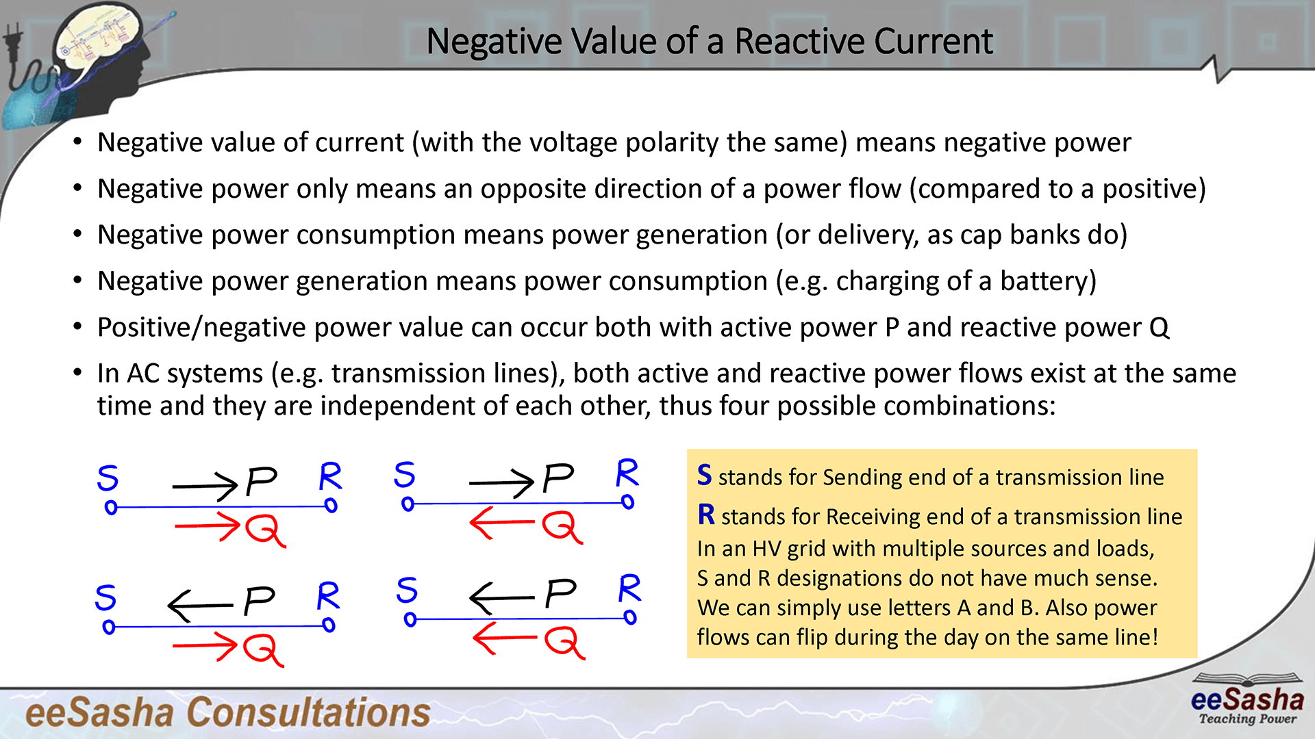
The negative value of a reactive current, assuming transmission line voltage remains the same (i.e. its polarity as a phasor does not change), actually means negative power flow. But, then the follow up question is: What is a negative power flow?
Negative power flow simply means an opposite direction of a power flow. Thus if we obtained positive power flow in one direction and now we are getting a negative value for the same power flow, that means the power has flipped the direction and now it flows in an opposite direction from earlier. Negative power flow value can be obtained for both active power P and reactive power Q.
So here are a couple of general examples of equivalent statements:
(the positive reactive power direction of flow is assumed from the transmission line towards the capacitor bank)
(Battery takes power instead of delivering it; the positive power direction is assumed away from the battery)
(the positive reactive power direction of flow is assumed from the capacitor bank towards the transmission line)
(Battery delivers power; the positive power direction of flow is assumed from the battery towards the load)
Note that a capacitor bank is normally considered to be a load. However, we treat it as a generator (or a source of reactive power) to eliminate the negative value of a power flow. Thus we say cap banks generate (positive) reactive power!
An electric battery is normally considered to be a source. Thus assumed (or positive) direction of power flow is away from the battery. However, when battery is being charged, the power flow is opposite and flows into the battery. Consequently, its value is negative. Negative power generation of a battery is actually a power consumption (battery is being charged).
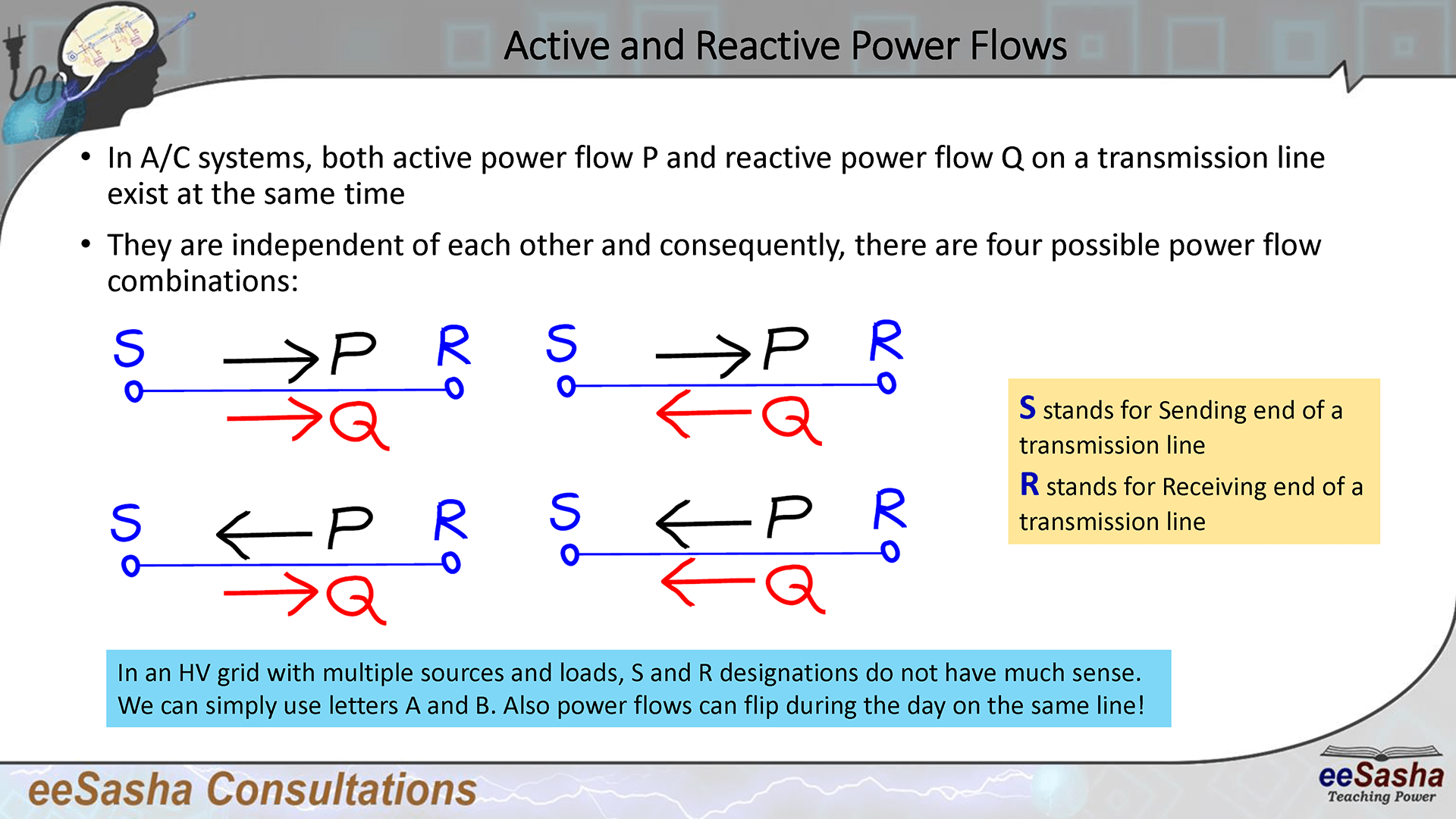
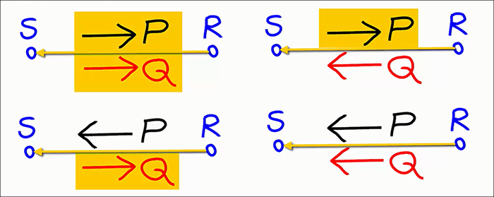
In an A/C power system, each transmission line carries both active and reactive power flows. Power flows can be positive or negative, and that holds both for active power flow P as well as reactive power flow Q. Since active and reactive power flows are independent of each other, there are four possible combinations of transmission line power flows:
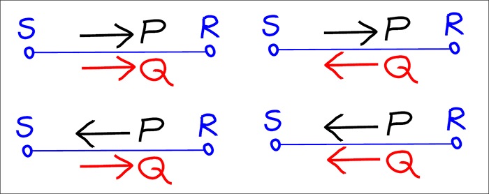
In the image above, we have a transmission line designated with S and R. Instead of a transmission line, the same could be a distribution line, a feeder or basically any connection or a link in a power system that we are interested in its power flows.
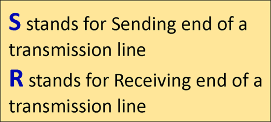
Each transmission line has two terminals and they are usually designated with S and R. S stands for Sending end of a transmission line, while R stands for Receiving end of a transmission line. Of course, this is just an arbitrary selection of designating letters.
In a High Voltage (HV) system, there is usually a large number of sources and loads. The system is basically a grid of transmission lines. In such a case, saying that one end is Sending end and the other end is Receiving end, doesn’t always make sense as powers can flow in any direction. If power flow changes, then Sending end may become Receiving and Receiving end may become Sending. In that case, we can also designate line terminals simply with A and B.
Also within the same transmission line, we can have perhaps Sending end sending power to the Receiving end in the morning and then power may flow in the opposite way in the afternoon.
Nevertheless, for the calculation reasons, we may still decide to stick with designating one end as Sending end (or associated quantities with a subscript S) and the other end as Receiving end (where we use subscript R).
Note that flow of a reactive power Q can be in the same direction as active power P, or the two may flow in opposite directions from each other. Which power flow is considered positive and which one negative, depends on a reference. Reference is basically an assumed direction of a power flow. Just like with any assumption, it can be true or false.
If actual power flow happens to be in the same direction as the one assumed (reference), then such power flow is considered positive
And similarly, but when the “assumption” is false:
If actual power flow happens to be in the opposite direction from the one assumed (reference), then such power flow is considered negative
The power flows as it flows. The power by itself is not positive or negative. Being positive means the actual flow is in the direction of assumed flow. Being negative means the actual flow is in the opposite direction of assumed flow. And this approach (or convention) holds not only for powers, but also for currents. As a matter of fact, the same holds for voltages as well. If we look within one cycle, the voltage flips its polarity and consequently, we have it as positive or negative voltage (A/C voltage).
It is important to emphasize that it is up to us what reference we choose. It doesn’t really matter whether we choose one assumed direction or its opposite. The only consequence is the sign of a power flow we end up with. However, once we make a choice of a reference, we must stick to it for the duration of our calculation.
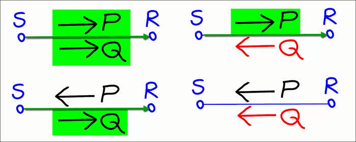
Normally, on a transmission line, we choose a reference directed from S towards R, as we assume that power would flow from Sending end towards the Receiving end.
The power flows highlighted in green are the positive power flows. Their actual direction is the same as the assumed direction (from S towards R). Power flows that are not highlighted would end up having negative values as their actual direction is opposite from the assumed direction.
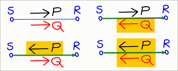
Thus, for the same reference (directed from S towards R), we can highlight in orange the negative power flows. They are negative as they flow in opposite direction from our assumed direction.
If for whatever reason, we change the reference and assume that power flows from Receiving end towards the Sending end, then all previously positive power flows become negative and all previously negative power flows become positive. Even though physically, those are the same power flows, their mathematical sign has changed when we picked an opposite reference.
In this case we chose the opposite direction as a new reference (directed from R towards S). As a consequence, all previously positive power flows are now negative (highlighted in orange).
So again, what is positive and what is negative is just a matter of reference, or what is our assumed direction (in case of power flows and currents) or assumed polarity (in case of voltages). Thus the convention we use or what we assume becomes important not only for our calculations, but also in terms of how we speak and how we express ourselves as engineers.
I help my students get clear understanding of various Electrical Engineering concepts. A question of negative values comes up quite often and I know from experience that students easily get confused with negative values in engineering.
Hopefully, you’ve learned something new today. If you’d like to become my student, you can schedule a consultation session of your own. Just go to eeSasha.com/help and pick the duration and time for your one-on-one consultation session!
As always, if you prefer watching videos, here is the “Active & Reactive T-Line Power Flows” video for you.
Note that audio used in this video clip is from an actual eeSasha consultation session that was paid for by a student. The slides have been modified for this video.
Thank you very much for your interest in Electrical Engineering and I hope to see you again! Below you can find the slides I used to develop this blog post and the video: